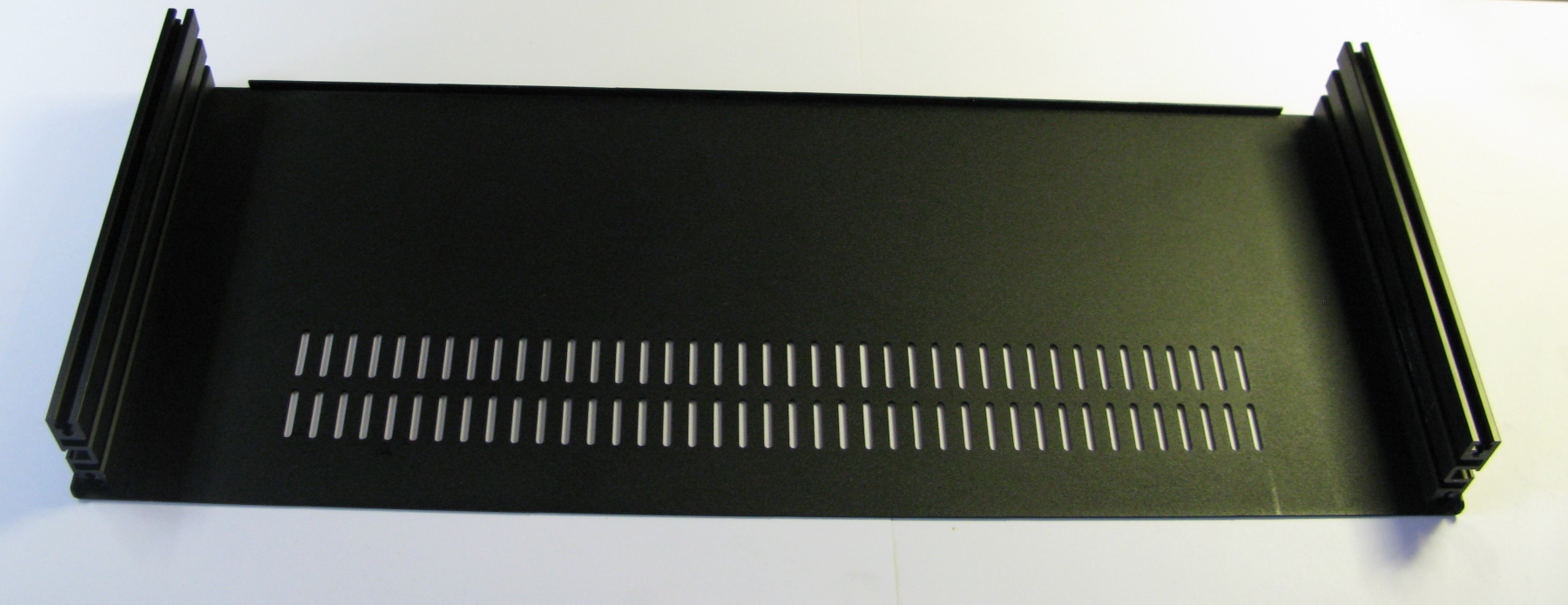
In this build we are using the parts below that you can buy from us and a 1U 19″ enclosure from Modushop (LINK) .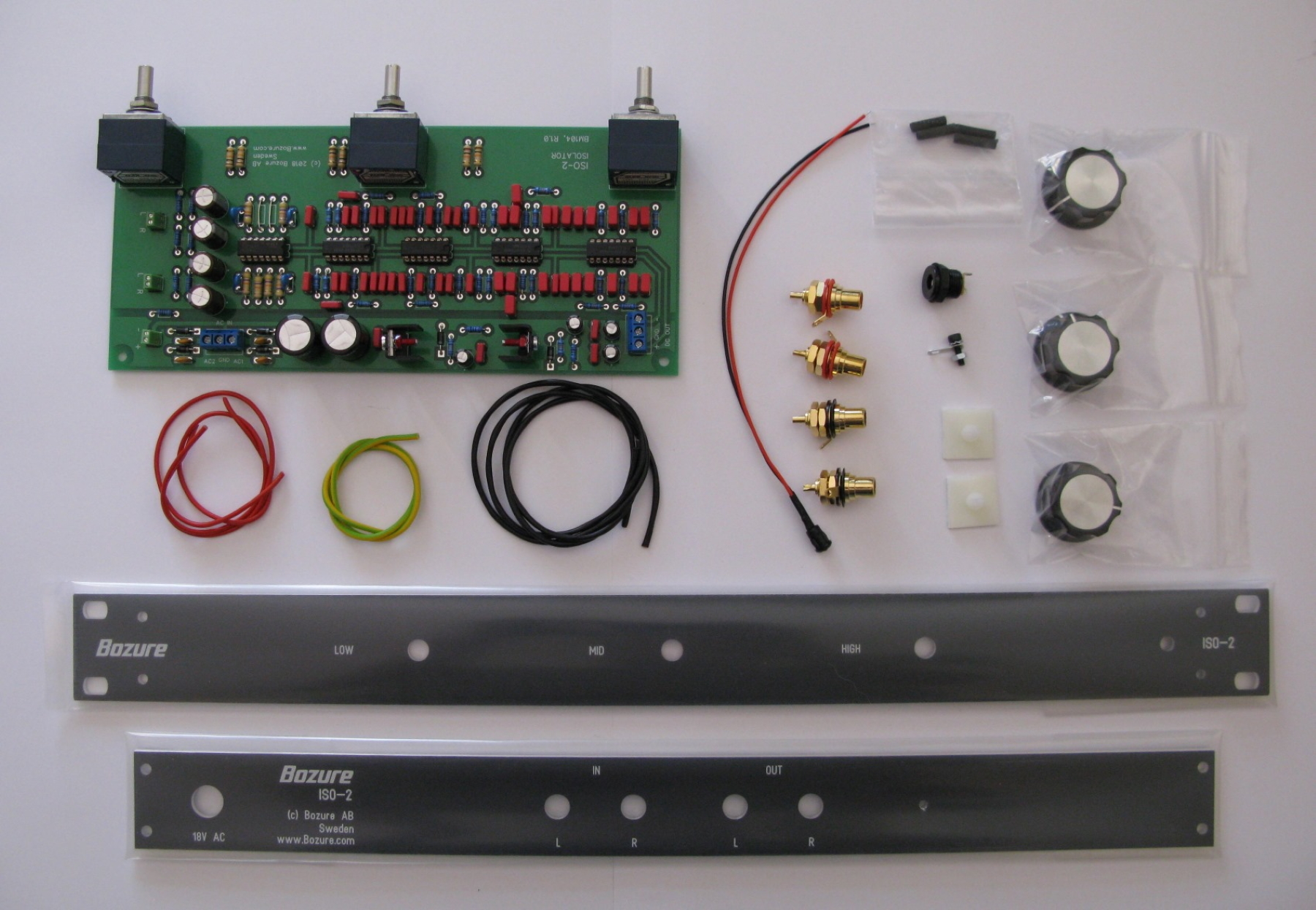
On the image is:
- ISO-2 PCB
- Black CNC processed front panel (Silver version also available)
- Black CNC processed rear panel
- Build parts kit (Parts list below).
Build Parts Kit
QTY – Description
3 – Knobs, 33mm.
2 – Neutrik Rean NYS367, Red Gold Plated RCA jack.
2 – Neutrik Rean NYS367, Black Gold Plated RCA jack.
1 – DC Jack.
1 – 3mm Ground Screw, Solder Tag.
1 – 3mm Red LED, LED holder.
2 – Spacer/Self-adhesive (PCB Holder).
2 – 40 cm Mogami Audio Cable.
2 – 25cm AC In wire.
1 – 30cm Ground Wire.
4 – Heat Shrink tubing.
You don’t have to do the build 100% like it’s described here but this is the way we do it.
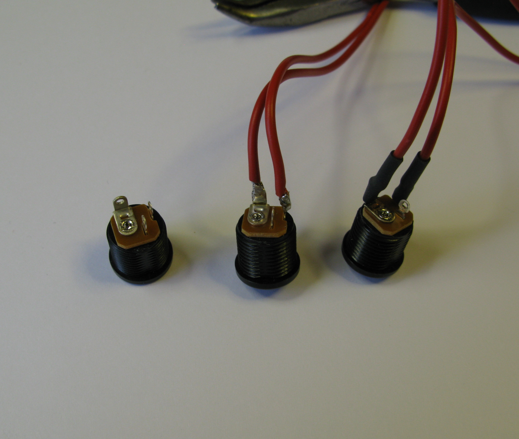
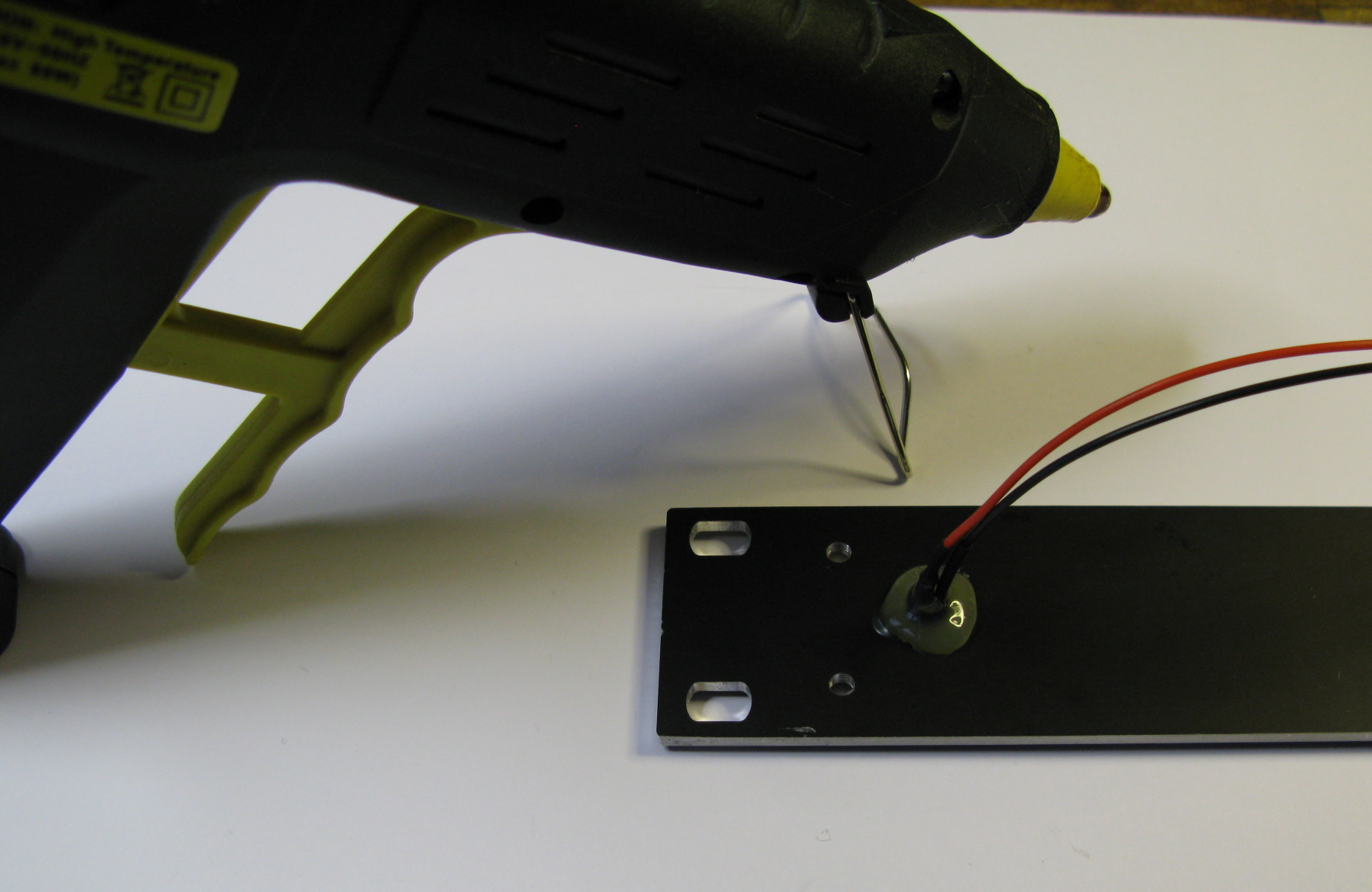
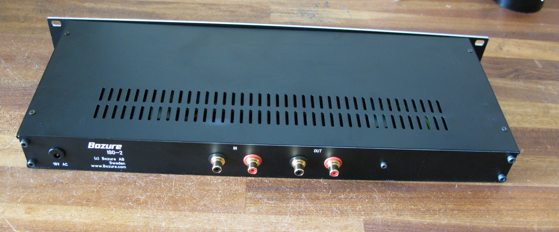
First solder the AC wires to the DC jack and add the heat shrink tubing to the wires. Finally add the DC jack to the rear panel. We use AC in here but ”DC-Jack” is just an often used name for this type of connector 🙂
Add the ground screw and the RCA connectors to the rear panel. Connect the ground wire to all off them, the other end of the ground wire will be connected to the PCB later.
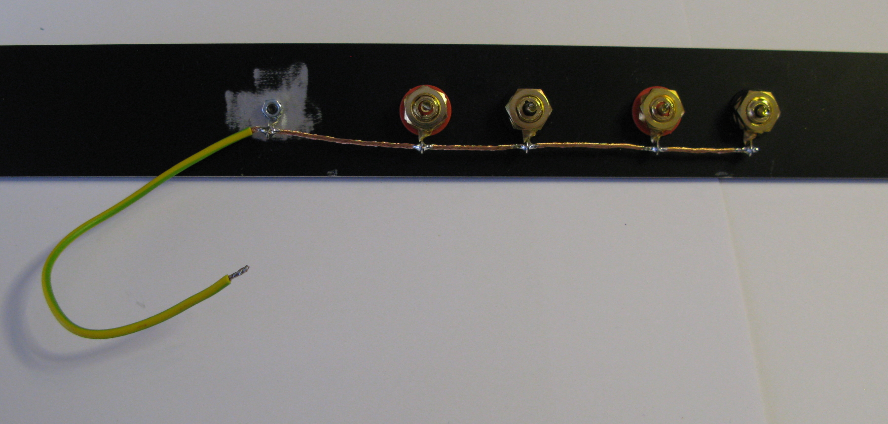
Connect (Solder) the audio wires to the RCA connectors and the cable ground wires to ground wire added before.
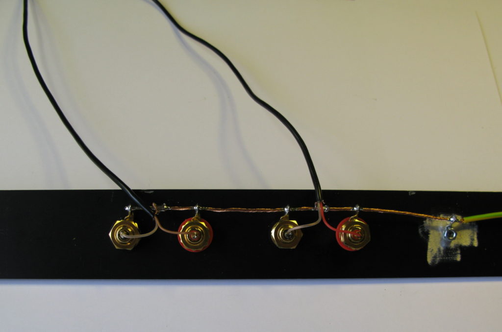
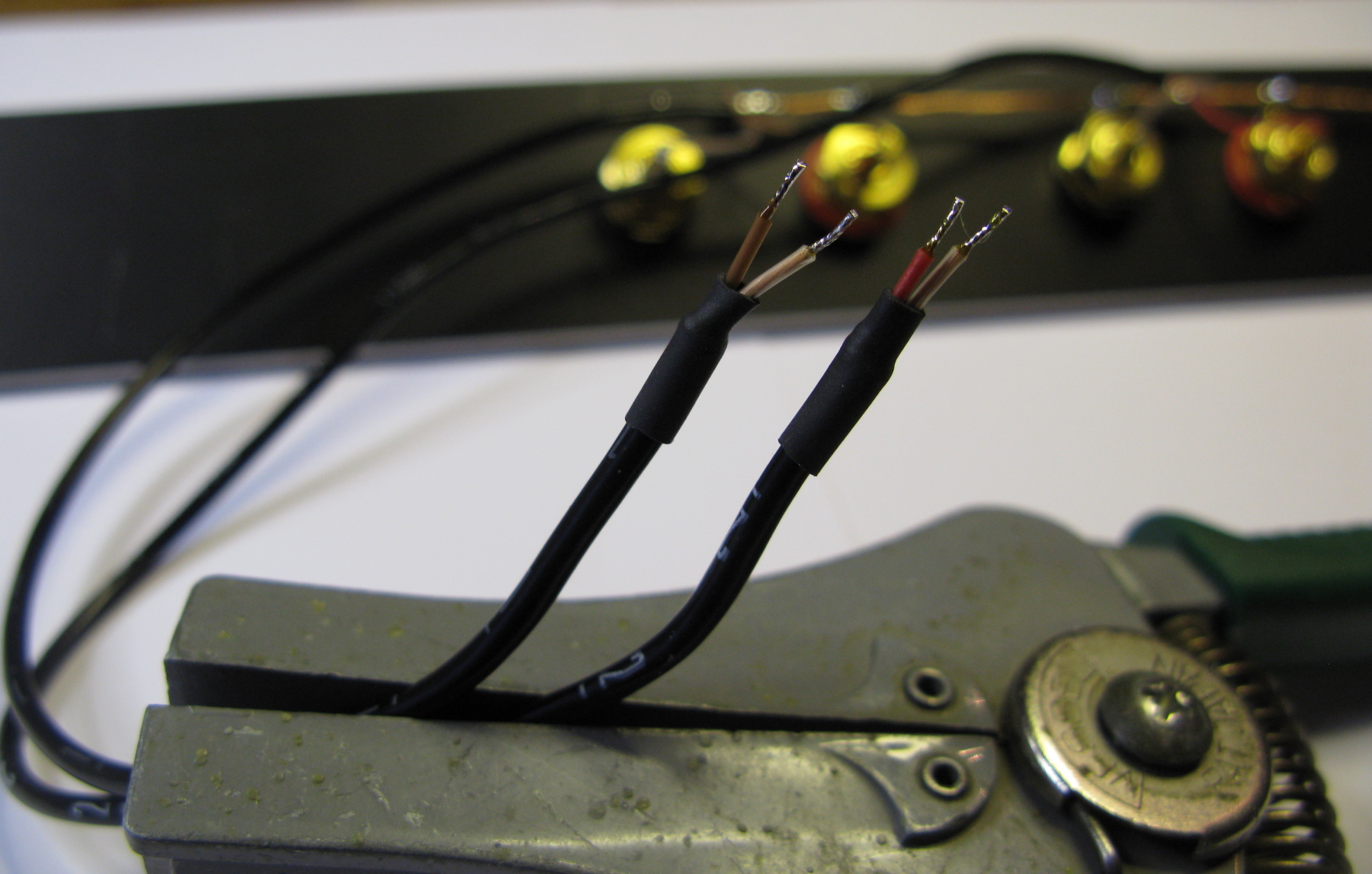
Prepare the other end of the audio wires to be connected to the PCB. We always add a lite solder on the last bit and add heat shrink tubing. Please note that this end of the audio wires should NOT be connected to ground on the PCB, if you do that you will create a ground loop.
Add the LED + LED holder to the front panel, you can also add a little glue on the rear side to hold it if you want.
Add the 2 plastic white spacers to the rear end of the PCB then add it to the front panel.
Add the 2 side profiles to the enclosure bottom panel.
Then connect the front panel to it. 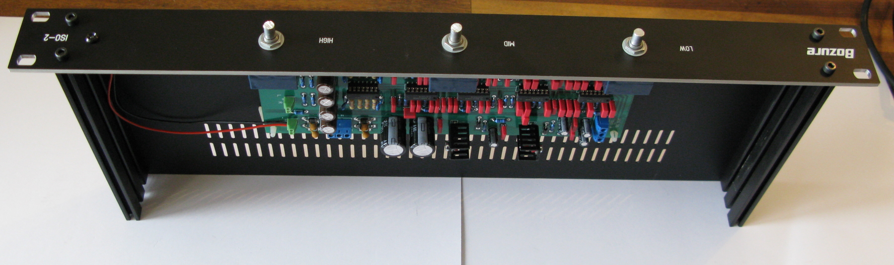
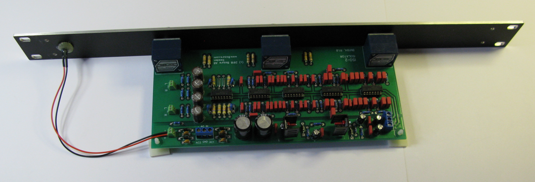
If you didn’t connected the LED wires to the PCB before do it now. RED to + and BLACK to – .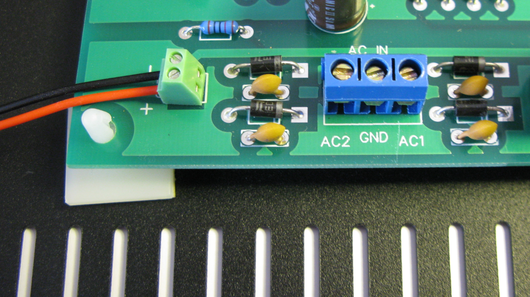
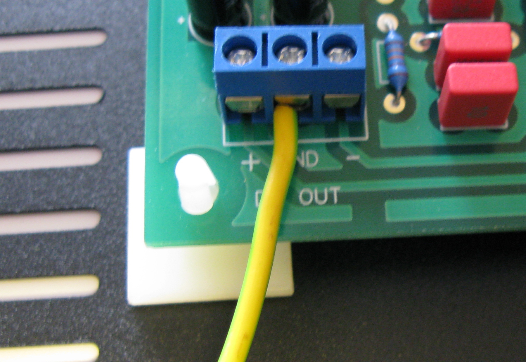
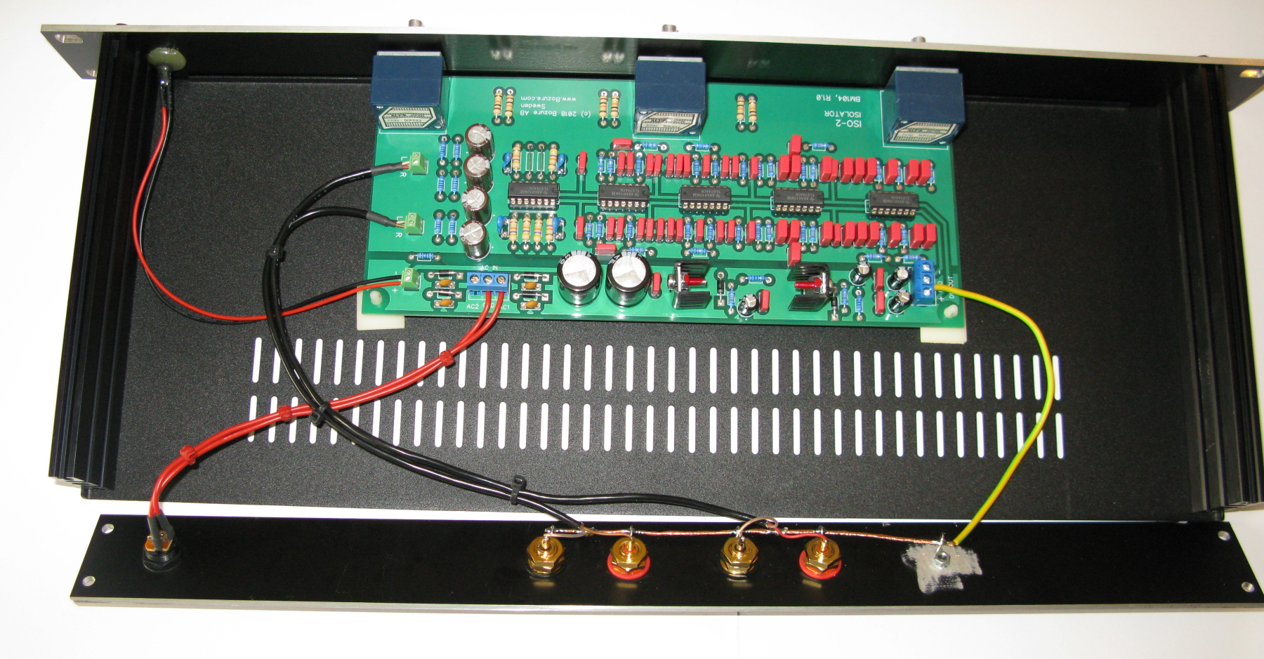
Connect the ground wire from the rear panel to the GND on the PCB connector.
Connect the 2 wires from the DC-Jack (external AC/AC adapter) to GND and AC1, AC2 is NOT used with an external single winding adapter. If you don’t want to use an external adapter but an internal mains transformer you can also do that. If you use a dual winding 18V AC-GND-18V AC out transformer then you also use AC2 in.
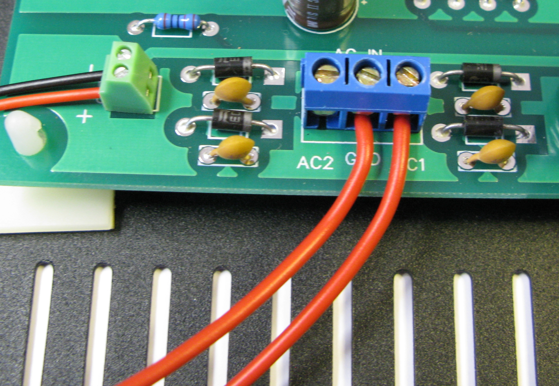
Time to connect the audio wires to the PCB, it should now look like this:
Add the 4 screws and nuts to the top enclosure panel.
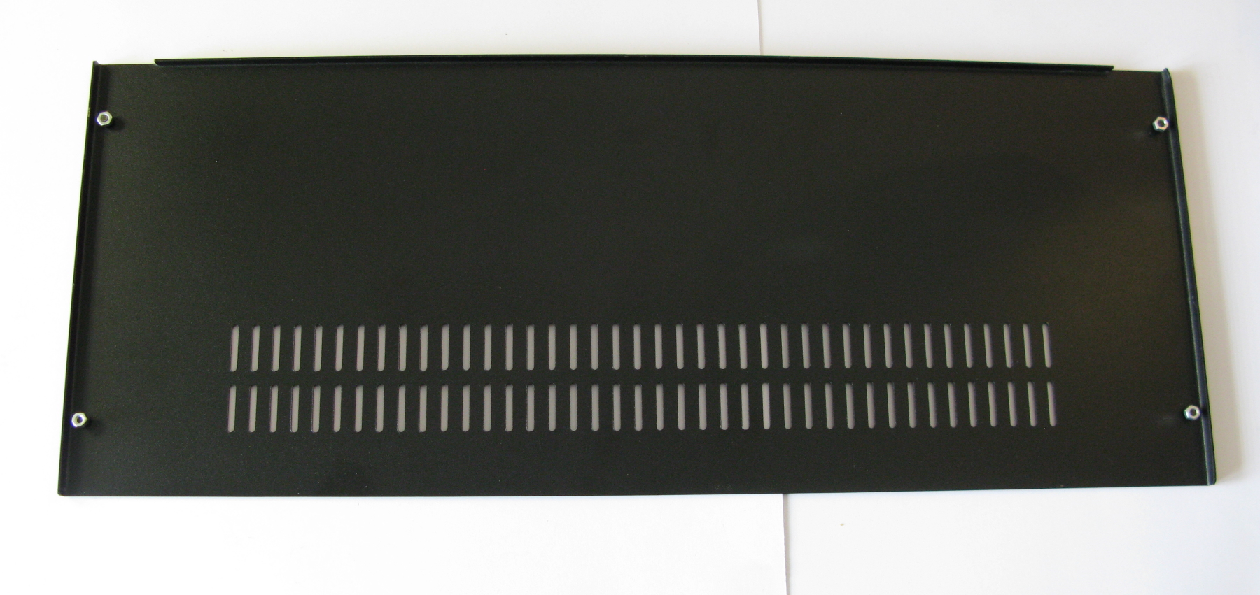
Slide in the panel from the rear to the side profiles
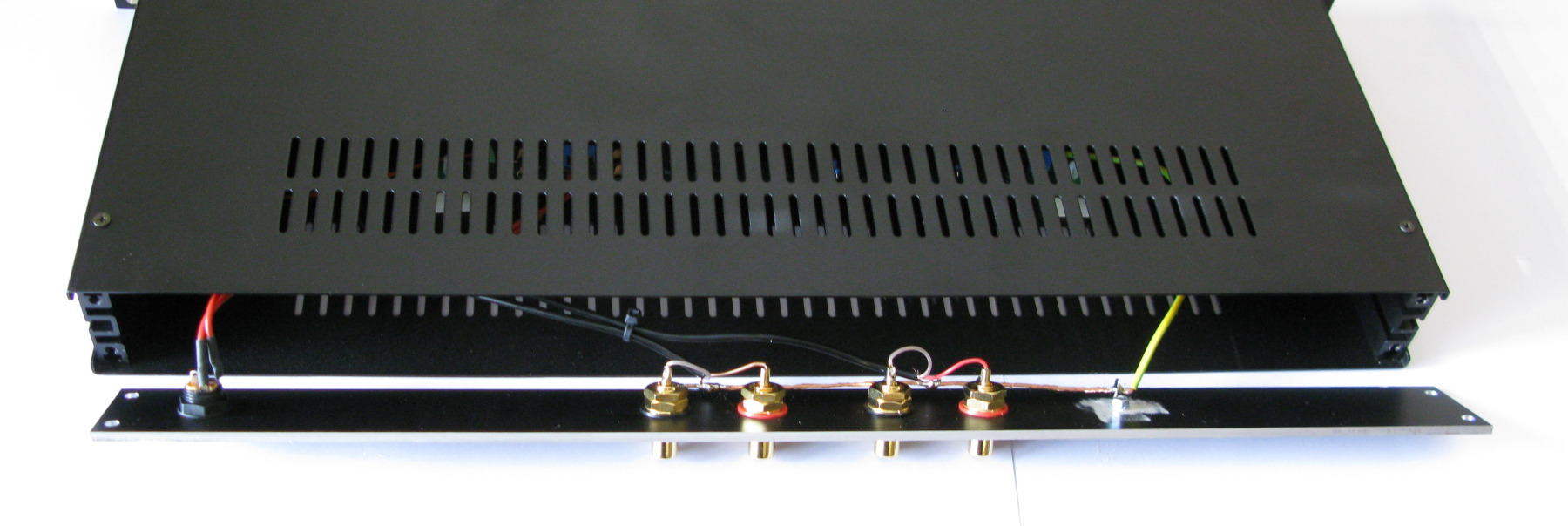
Then just add the 4 last screws that holds the rear panel.
Done, time to start having fun with it 🙂
Still got questions ?? Just contact us via email or on Facebook and we will help you 🙂